3D Modeling
Most of the bricks used in the strip were modeled over a two-week period, early on. Most of them are fairly simple constructs, of course. In fact, most of the walls, desks, and so forth in the strip are simple rectangle blocks without cut-ins or studs. The basic philosophy in 3D rendering holds here – if geometry is not visible in the scene, don’t include it. This saves time in modeling, texturing, and reduces the computer resources required to manipulate or render the scene.
Tech Notes
Initial 3D work on the strip was performed on a Lenovo laptop, but shifted over to my shiny, new MacBook Pro after the first few weeks. (Yes, I work for Microsoft. Yes, I own a Mac. More than one, actually. Oh well – I was pHil before I was a blue badge). I use a late 2011 MacBook Pro, with dual quad-core 2.0 GHz i7 processors, and 8GB of RAM.
My programs of choice are 3D Studio Max 2009 and Photoshop CS2. Sure, both are out-of-date, but I’m too cheap to upgrade. To run these fairly hungry programs, I run Boot Camp rather than fiddling with any virtualization programs. Bare metal all the way, baby!
There are other programs that could certainly produce similar or identical output, so while I use these programs on a Mac that thinks it’s a PC, you can use your own preferred mix to do this stuff. Instead of 3DS Max on the PC, you could use Maya on Windows, Mac OSX, or a Linux OS. Cost is similar, results are similar, the skillset – not so much. I never got the hang of Maya. You could also use Blender, which is open-source, free, and cross-platform. In my opinion, Blender’s probably a great way to get started in 3D modeling and rendering. I tried it a long time ago, and never really dug in too deep. The product has improved drastically over the years – I recommend trying it out as an entry point.
Photoshop also has many alternatives, including a couple free ones. The GIMP is open-source and cross-platform as well, and in my experience can do pretty much anything Photoshop can, although I’ll be lambasted for saying so. If you’re on the PC side of the ‘verse, you can check out Paint.NET. I recommend it as a streamlined program, which can do all the basic image editing stuff I’ll cover – layer effects, sizing, etc. It’s basic, but it’s good.
I apologize if the terminology I use in these articles points too heavily toward the software packages I use. If that is ever the case, I’m confident that the principles demonstrated are universal across similar applications, so feel free to adapt these tutorials to your program of choice.
Scale and Measurements
Have I sat around for hours with LEGO® bricks and a micrometer? Sure! I mean, who hasn’t? But, I don’t want to turn this section into a pedantic measurement-heavy math fest. Just a quick description of how I configured the “world” in 3DS Max. I use generic units instead of metric or English systems and “actual” measurements. I started to use metric at an early stage, and keep every measurement precise based on that, then tried using the LDU (which is 1/20 of an L, or LEGO unit), but my brain soon melted. Generic units rule.
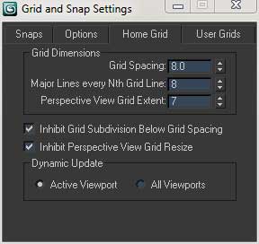
I set up my grids based on an 8-unit scale. This is because the basic 1×1 brick is 8mm by 8mm in its footprint, and most other measurements (9.6mm tall, for example) are in multiples or decimal factors of 8. All of this makes it straightforward to set up a “snap-to” grid that fairly well approximates the physical bricks we use. So, my basic 1×1 brick is 8 units wide, 8 units deep, and 9.6 units tall. The stud is 5 units in diameter, and 1.7 units in height. So, I’m using generic units, but they have a direct correlation to the mm scale.
(Note: You can click on the image thumbnails for a closer view of the tutorial screenshots.)
Simple bricks
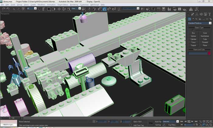
Drop the Cow! employs a library of common bricks, from which I build whatever props & sets might be required for each strip:
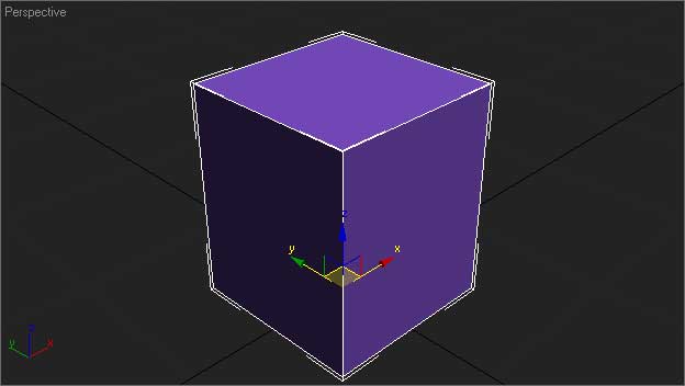
This library continues to grow on a weekly basis, but it all started with the basic, 1×1 brick I mentioned. The first step in creating the 1×1 brick is to create a simple box, 8x8x9.6 units:
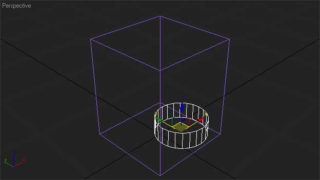
Add a cylinder for a stud, 2.5 units in diameter, and 1.7 units tall. Pick a resolution that will render a smooth side surface – I chose 24 segments for this example:
The stud is in the wrong place, so use the align tool to center it on the box, and also to line up its Z-axis minimum with the Z-axis maximum of the box:
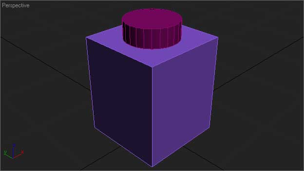
Starting to look like a brick! A couple things we need to do before it will really render very well, though. Both the box and the cylinder have very sharp edges, which would lead to unconvincing renders, so we’ll add a slight bevel to all the edges. To do this, we need the box and cylinder to be editable objects – so we can manipulate the edges, faces, and vertices. I prefer to work in what Max calls an “Editable Poly”, although you can use the editable mesh or editable patch object types, or even NURBS if you’re so inclined. I’m not… Anyway, I convert the primitives into editable polys. Now, I can enter sub-object editing mode and select all the edges in the box:
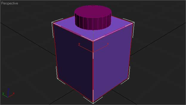
Slap a 0.1 unit chamfer or bevel on each edge:

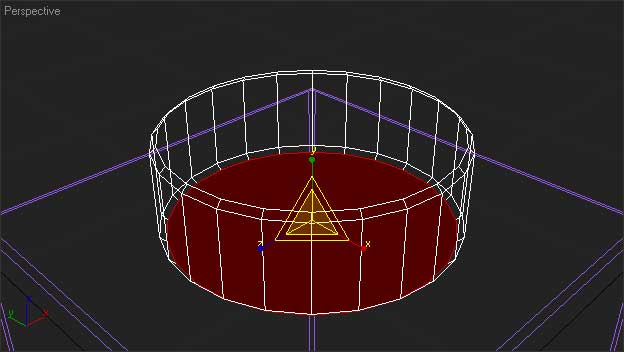
And repeat for the cylinder, but only on the edges along the top & bottom circular faces:

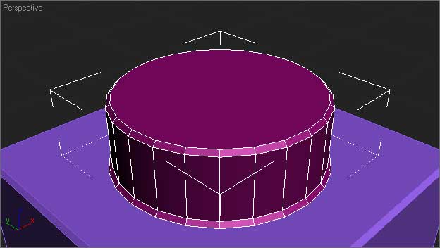
Next, we need to modify the chamfered transition from brick to stud. Select the bottom face, and scale it on X and Y axes to make it just a little bit bigger as it contacts the brick’s top:
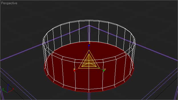
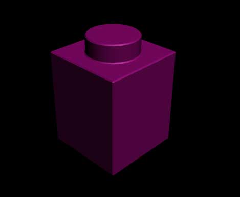
Almost done. Now, we’ll merge the two objects into one. I use the “Attach” tool (or method, for you object-oriented folks out there ?) to combine both polys into one. Add a Smooth modifier set to “Auto Smooth”, and the brick is finished!
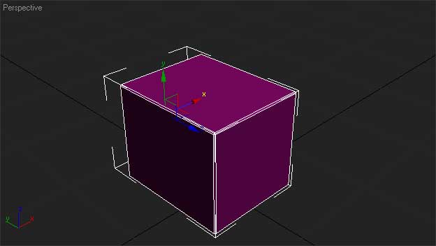
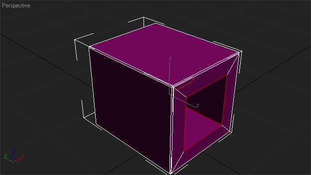
Pretty much finished. However, in some shots, the open bottom of the brick needs to be shown. Right now, this presents a problem:
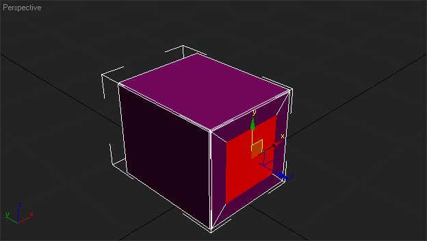
Yeah – no hole in the brick’s bottom. We’ll rectify this with some additional edits. First, select the bottom face, and use the inset method to create a smaller, inner face equivalent in diameter to the stud on top. 1.4 units comes out to be pretty close:
With the smaller face still selected, extrude the face inward toward the top of the brick. I used an extrusion setting of -8 units:

The last remaining bit is to add the chamfer to the newly exposed edges along the inside of the extrusion. Switch to edge selection mode and select the new edges:
Add the 0.1 unit chamfer, as before, re-apply the Auto Smooth modifier, and we’re done:
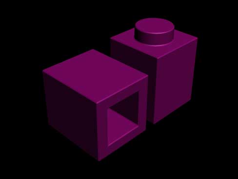
Right, that was pretty straightforward, but it covers all the main tasks/topics involved in creating simple bricks: scale, dimensions, primitive objects (the box and cylinder), type conversion (from primitive to editable poly), and poly modeling techniques (attaching other objects, sub-object selection, face inset, extruding, chamfering). There are other techniques, of course, but I leave it to you to experiment with them. These techniques are all I used to generate the following additional bricks of varying complexity:
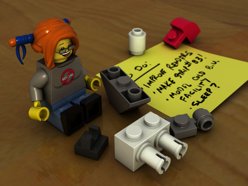
Even the minifigs didn’t require much more than this, although some of the hair pieces have proven pretty difficult. I expect I’ll do an “advanced/organic modeling” tutorial later to finish this up.
😀
Umm, I’m somewhat concerned by the lack of comments on this page telling you just how AWESOME this is! Very, very clever 🙂
Thanks! Keep talking like that, and I might get around to posting the rest of those tutorials I promised 😀
Silly me. I didn’t realize you did all this on computer. Very cool, though.